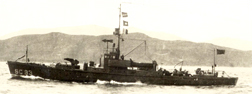
Recently Jack Hudock passed along to me some notes from Normand Boucher (see The Wireless History Hacker) on the bedspring antennas on US submarine chasers in WWI: the antennas strung overhead and connected with a lead that runs up the front of the pilot house.

Antenna shield. A section of a photo scan submitted by Jim Gunther,
whose grandfather, Charles Gaffney, was a crewman on SC C 79.
Full image on this page.
I hope Normand will post sometime on this in his blog (if you find a post, please send it to me), and thought I'd pass along a few points from his notes. First, these were "T" or flat-top antennas, and the design was based on the radio wavelength in use and the resulting antenna length needed. A longer antenna is needed for a lower frequency, so the wires were strung overhead on ceramic insulators and tied together at the ends. Overall, the set of horizontal wires creates an antenna that functions as if it were longer.
The position of the lead, as you might guess, was based on the location of the radio room, which is why you see it attached off center. Normand notes that the overall design is "an inverted-L or end-fed T antenna.
--Todd Woofenden, editor